Next: XKB Programs Up: An Unreliable Guide to Previous: Choosing an XKB Configuration Contents
Working through the XKB configuration files is a bit of a chore. In most cases you don't have to. There are perfectly adequate pre-packaged configuration files already present. Before you even think of wading through this section, have a look at section 3.1.
However, at the end of the day, you may have to roll your own. Or you may have to understand what's in the files so that you can pick one.
The main files are in the keycodes, types, compat, symbols and geometry subdirectories, corresponding to the components of the same name. The keymap, rules and semantics subdirectories contain ways of grouping the main components together into neat bundles.
XKB configuration files are all structured in a similar way. A single configuration file contains information on a group of similar items. The file can contain a number of variants that contain variations on a theme.
Each variant has the following syntax: a set of options, a type and a name, followed by the variant information in braces and a semi-colon. The type describes the sort of information present, eg. xkb_symbols for symbols configuration. The name is enclosed in quotes and contains the variant name, eg. "pc102" -- see section 3
Within each variant is actual configuration information. This information uses whatever keywords and information is appropriate to the type at hand. It is also possible to include information from other files and variants. There are two ways of including information: you can include or augment. If you include, using the syntax include "file(variant)" -- note the lack of a semi-colon -- then the information from the included file overrides any configuration information that already exists. If you augment, using the syntax augment "file(variant)" then the information is only added if it doesn't override something that already exists. In both cases, the file argument is assumed to come from the same base directory as the type, eg. symbols files come from the symbols directory.
The configuration file syntax also allows inheritance of information wherever possible. Contexts and groupings are enclosed in braces. Information from parent contexts are inherited. For example, in a geometry file, the top level of some geometry might have shape.cornerRadius = 1; to set the level of corner roundness. This piece of shape information is inherited by any defined shapes, although it can be overridden for a particular shape.
|
The options set the various levels of visibility and function that each variant shows. The options are summarised in table 1. The *_keys options are used in the symbols component and are used to provide hints as to what partial symbol maps contain.
The key codes files map a keyboard's scan codes onto useful symbolic forms. These files are the first point of contact between a keyboard and the XKB system. After that, things tend to become keyboard independent, focusing on the sorts of symbols that you want to produce and the behaviour that you want out of the keys.
The basic structure of a key codes map is something like:
xkb_keycodes "basic" {

    minimum= 8;
    maximum= 255;

    <TLDE> =  49;
    <AE01> =  10;
    <AE02> =  11;
...
    indicator 1 = "Caps Lock";
    indicator 2 = "Num Lock";
...
    alias <AE00> = <TLDE>;
};
The xkb_keycodes "basic" gives the type of the component (key code map) and the variant name (basic).
Following that, the minimum and maximum lines give the minimum and maximum key codes that the keyboard generated. If not all the key codes are used, that's not a problem.
The lines of the form <AE01> = 49; map a keyboard key code (49 in this case) onto a symbolic key name (<AE01> in this case). These lines associate key codes with the names that will be used in components such as a symbols component.
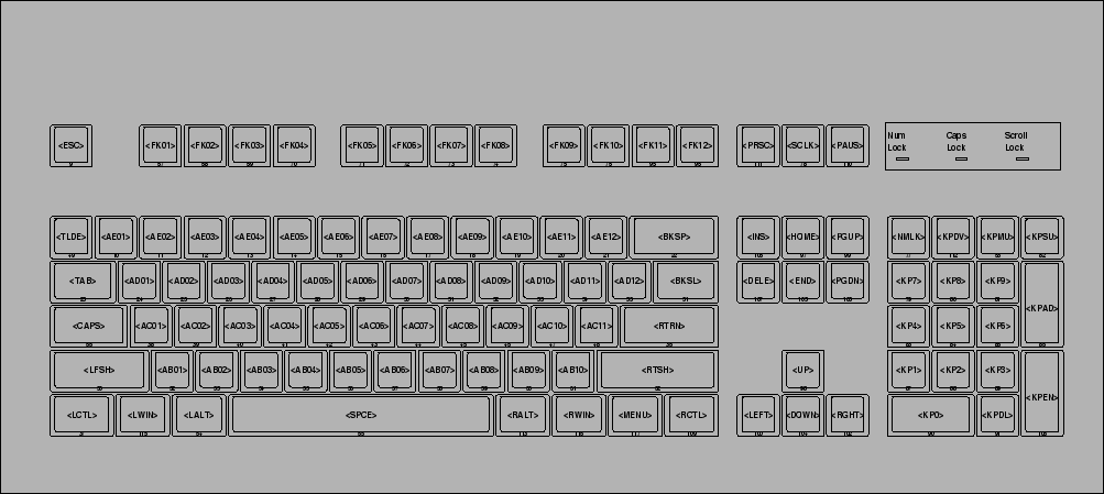
The convention used is to explicitly name shift and escape-like keys, but to name ordinary keys by a positional code. Hence, <AE01> is actually what would be the 1/! key on an ordinary qwerty keyboard. However, the left shift key is denoted by <LFSH>. This convention is, presumably, so that Dvorak-like keyboards can be sensibly specified. The keyboard codes are notionally based on a conventional qwerty keyboard and are shown in figure 2
The lines of the form alias <AE00> = <TLDE>; allow alternate names to be associated with the same key. In the example given, the tilde key, associated with the key code 49 in this keyboard can also be referred to as <AE00> as well as <TLDE>. This facility is useful if you want to refer, sometimes, to ``the leftmost key of the top row'' rather than ``the tilde key''.
The lines of the form indicator 1 = "Caps Lock"; enumerate the indicator LEDs that the keyboard has. I think that the name of the indicator is important, rather than the number, since this is referred to in other components, such as the compat component. It's possible that the indicies refer to the numbering of the indicators in the keyboard's hardware. The problem with this interpretation is that it violates the symbolic = concrete formulation used in the rest of the file.
Virtual indicators are also possible. I have no idea what these do.
The symbols component maps the symbolic key codes created by the keycodes component onto whatever symbols the user wants to produce. It's at this point that peculiarities such as national character sets, the position of control keys and other things make an appearance. The symbols maps also handle the effect of groups and levels -- see section 2.2.
Some of the symbols generated by a symbols map are not used directly, but are passed on to the compat component for further processing.
A symbol map file may look something like this:
partial alphanumeric_keys
xkb_symbols "basic" {

    name[Group1]= "US/ASCII";
    key <ESC>  {        [ Escape                        ]       };
...
    key <TLDE> {        [ quoteleft,    asciitilde      ]       };
    key <AE01> {        [         1,    exclam          ]       };
...
    modifier_map Shift  { Shift_L, Shift_R };
...
};
The first part of the symbol map, partial default alphanumeric_keys xkb_symbols "basic" simply declares that this is a symbol map named basic, along with a few options. The partial option indicates that this map doesn't cover a complete keyboard, just some interesting section of it. The alphanumeric_keys option describes which section of the keyboard is being covered. Multiple *_keys options are allowed, but if none are specified, then the map is assumed to cover a complete keyboard.
The name[Group1]= "US/ASCII"; statement gives a name to one of the keyboard groups. Other groups can be specified by using the same syntax but with a different group name.
The line key <TLDE> { [ quoteleft, asciitilde ] }; describes a single mapping from a key code (<TLDE> in this case) to a group of symbols (` and in this case). Symbols are named, using the symbolic names from the /usr/X11R6/include/X11/keysymdef.h file, as described in section 2.4. A pair of symbols enclosed in brackets indicates a pair of symbols separated by a shift level; pressing the Shift key usually shifts between two levels, but the types component can override this. If a single symbol is enclosed in brackets, then this symbol is used always, independent of the level.
The key code { [ symbol, symbol ] }
syntax is a short form of a more general syntax that allows more
flexible specification.
Inside the braces, it is possible to use the syntax
group[groupname] = [ symbol, symbol]
instead, with the various statements being separated by commas.
This syntax is needed when extra information, such as type information
is being specified for the key -- see section 4.3.2.
XKB is pretty flexible with respect to modifier keys, pretty much allowing anything which looks like a modifier key to be used as one. The types and compat components handle the interpretation of various combinations of keys. However, there are many X11 programs that need to keep track of modifier key status (eg. a flight simulator) and expect input from the old modifier combinations of Lock, Shift, Control and Mod1-Mod5. The line modifier_map Shift { Shift_L, Shift_R }; maps the left-Shift and right-Shift keys onto the old-style Shift indicator, so that older programs have some idea as to what is going on.
Multiple groups can be specified by including other lists of symbols after the first list, with each list separated by commas. Each group needs to be named. The resulting configuration looks like:
name[Group1]= "US/ASCII";
name[Group2]= "Russian";
...
key <AD01> { [ q, Q ],
             [ Cyrillic_shorti, Cyrillic_SHORTI ] };
In this case, two groups are defined. For the Q key, two lists of symbols are given, one for the US/ASCII group and one for the Russian group.
It is also possible to specify multiple groups using the long-form syntax. For example:
key <AE11> {
    symbols[Group1]= [ minus, underscore ],
    symbols[Group2]= [ minus, questiondown ]
};
It is also possible to define a partial symbol map that only provides mappings for some higher, non-default group. In this case, the symbol mappings for the lower-level groups are empty. These sort of symbol maps can be included in with more basic maps, to allow a For example, the following defines a group 3 (only) mapping:
key <AD01> { [], [], [ q, Q ] };
The types component specifies how differing levels are to be handled for various keys. By default, it would appear to be the case that most keys are automatically given a two-level or alphabetic type (see section 4.4).
In some cases, however, it may become necessary to explicitly associate level-behaviour with a key. In this case, the type and symbol map needs to be given explicitly, for example:
key <PRSC> {
    type= "PC_SYSRQ",
    symbols[Group1]= [ Print, Sys_Req ]
};
In this case, the <PRSC> key code is given an explicit type (PC_SYSRQ). The group 1 symbols are then explicitly given, using the long syntax.
Most modifiers are simply specified by including the suitable symbol names; modifier keys have names, the same as any normal key. For example, the left-Control key is called Control_L. In most cases, a separation is maintained between left- and right-hand versions of the keys, even if you want them to do the same thing.
The compat component expects certain virtual modifiers to be defined, so that certain logical behaviours (eg. how to switch groups) can be neatly defined -- see section 4.5. If a modifier key contributes to a virtual modifier, then that needs to be specified, using a virtualMods = name statement in a key definition. The long-form syntax needs to be used, for example:
key <RALT>  {
    symbols[Group1]= [ Mode_switch, Multi_key  ],
    virtualMods= AltGr
};
Generally, holding the Control key down and typing an alphabetic key is expected to produce a low-value control-key character, eg. Control-H produces ASCII 8. Which keys produce which control characters is, essentially, hard-wired and specified in appendix A of the XKB protocol.[3].
Which keys are control keys is specified by using the modifier_map statement to map keys onto the Control modifier. For example:
modifier_map Control { Control_L };
There are a huge array of ``symbols'' that are intended, instead, to be used to control various parts of XKB or X11. The most obvious examples are the modifier keys, discussed in section 4.3.3. In addition, there are lots of symbols designed to do things like launch a web browser or be combined with other symbols. All of these symbols have character codes.
In addition, there are pseudo-keys such as Mode_shift that are not intended to actually produce symbols. These keys are usually consumed by the compat component to produce actions.
Types provide information as to the levels available for various keys and how to shift between the levels. Each key can have its own type and have differing numbers of levels and differing ways of switching between levels; eg. only alphabetic characters are shifted when the Caps Lock key is on.
The type that a key has can either be explicitly given in the symbols component -- see section 4.3.2 -- or assigned automatically. If a type is not explicitly specified, then the following rules apply:
An example types component is shown below:
partial default xkb_types "default" {
    virtual_modifiers LevelThree;

    type "THREE_LEVEL" {
        modifiers = Shift+LevelThree;
        map[None] = Level1;
        map[Shift] = Level2;
        map[LevelThree] = Level3;
        map[Shift+LevelThree] = Level3;
        level_name[Level1] = "Base";
        level_name[Level2] = "Shift";
        level_name[Level3] = "Level3";
    };
};
The virtual_modifiers LevelThree; line describes the virtual modifiers that are to be used. These are modifiers that have an equivalent virtualMods = LevelThree somewhere in the symbols component, or a virtualModifier = LevelThree; somewhere in the compat component. The standard shift modifiers do not need to be specified.
The modifiers = Shift+LevelThree; line gives the set of modifiers that need to be considered for this particular type.
The map[Shift] = Level2; line indicates that level 2 is to be used when the shift key is down.5
The lines such as level_name[Level2] = "Shift"; give suitable names to each level. These lines are useful when you wish to do things like print out key maps. Otherwise, they have no direct effect on anything.
The compat component is a shortening of ``compatibility map''. This seems like a rather odd name for the component that is largely concerned with translating certain key combinations into actions, rather than symbols. But there you are.
Compatibility maps intercept certain combinations of keys, usually modifier keys of various sorts. These keys are translated into various actions, ranging from changing the internal state of XKB (eg. selecting the current group) to moving the mouse pointer. Usually, these key strokes are consumed by the compatibility map and disappear -- although they can be passed on to other components or into the outside world.
Compatibility maps also control the various indicator lights that are displayed.
|
|
The basic structure of a compatibility map is a set of interpret statements that map combinations of keys onto action statements. The action statements usually consist of some kind of verb and a set of fields to act upon. The actions are listed in table 2 and the fields in table 3. Not every field is used in each action, table 4 lists the fields available for each action.
A major part of many compatibility maps is the handling of modifier keys. These keys need to be translated into concrete actions -- group and level shifts, etc. -- as well as locked or latched. A normal (unlocked, unlatched) modifier key has an effect only while it is being held down. A locked modifier key is on until another key press releases it. A latched modifier key is on until another key is pressed, at which point the modifier is released.
A compatibility map looks something like:
default xkb_compatibility "basic"  {
    virtual_modifiers NumLock,AltGr;
...
    interpret.repeat= False;
    setMods.clearLocks= True;
...
    interpret Shift_Lock+AnyOf(Shift+Lock) {
        action= LockMods(modifiers=Shift);
    };
...
    group 2 = AltGr;
...
    indicator.allowExplicit= False;
...
    indicator "Caps Lock" {
        whichModState= Locked;
        modifiers= Lock;
    };
...
};
The default xkb_compatibility "basic" line gives the usual option, type and name information, same as any other component.
The virtual_modifiers NumLock,AltGr; line lists any virtual modifiers that might be set or examined
The interpret.repeat= False; and setMods.clearLocks= True; lines set one of the default fields for part of the compatibility maps. Both actions (eg. setMods) and certain syntax (eg. interpret) can have defaults set.
The line interpret Shift_Lock+AnyOf(Shift+Lock) tells the compatibility map what keys trigger actions. The first part (Shift_Lock) is the name of the key that has been pressed. The second part gives the modifier keys that need to be set to trigger this action. In this case, either the Shift or Lock modifier needs to be set. Specifying modifier keys is optional, or specified as Any. If more than one key is possible, as above, then AnyOf, AllOf, Exactly or AnyOfOrNone are possible combinations of modifiers.
The line action= LockMods(modifiers=Shift); gives the action that the keys in the interpret line are supposed to produce. In this example, LockMods is the action (see table 2) and modifiers is the field (see table 3) to be set. Multiple fields can be separated by commas. The right hand side of a field assignment can be an expression with the usual arithmetic operators. For numeric fields, instead of straight = assignment, a signed value indicates a relative change -- eg. group= +1 increments the current group.
The line group 2 = AltGr; maps a group value onto a modifier state. This is for the benefit of older programs that know nothing of the wonders of XKB. In this case, being in group 2 means that the AltGr modifier is set.
The indicator "Caps Lock" line declares the conditions under which an indicator is lit. The name of the indicator (``Caps Lock'') in this case is mapped onto the indicator names given in the keycodes component -- see section 2.3.
The line whichModState= Locked; gives the state that the particular modifier needs to be in to activate this indicator. Possible states are Base, Latched, Locked, Effective, Any or None.
The line modifiers= Lock; gives the list of modifiers that need to be in the correct state to activate this indicator.
The geometry component is probably the most useless part of XKB. So we're going to do it last. Essentially, this component supplies information on the physical layout of certain keyboards, so that programs such as xkbprint can produce sensible looking output.
Naturally, for something so trivial, the geometry files are some of the most complex. A sample file is shown below:
default xkb_geometry "pc101" {

    description= "Generic 101";
    width= 470;
    height= 210;
...
    shape.cornerRadius= 1;
...
    shape "NORM" { { [ 18,18] }, { [2,1], [ 16,16] } };
...
    solid "LedPanel" {
        shape= "LEDS";
        top=  52;
        left= 377;
        color= "grey10";
    };
...
    indicator "NumLock"     { left= 382; };
...
    text "NumLockLabel"     { left= 378; text="Num Lock"; };
...
    section "Function" {
        top= 52;
        row {
            top= 1;
            keys {  { <ESC>, color="grey20" },
                    { <FK01>, 20 }, <FK02>, <FK03>, <FK04>,
...
    alias <AC00> = <CAPS>;
...
};
The default xkb_geometry "pc101" line contains the usual options, type and name declaration. The description= "Generic 101"; line gives a descriptive name to the keyboard.
The line width= 470; gives the total width of the keyboard. All lengths in geometry declarations are multiples of 1mm, so 470 is 47cm.6
The line shape.cornerRadius= 1; defines a default setting for a shape field. In this case, the corner radius of a join is set to 1mm. Other items, such as solids, have other fields, these are listed below.
The shape "NORM" { { [ 18,18] }, { [2,1], [ 16,16] } };
line declares a shape.
A shape is a named drawing outline that can be used elsewhere to
draw something like a key or an indicator.
This shape defines the look of a normal key.
All coordinates are from the upper-left corner and increase
rightwards and downwards.
The origin of a shape is always ![]() in the upper-left corner;
this position is shifted to wherever a shape needs to be drawn.
A shape consists of a list of outlines, with each outline representing
a closed figure.
An outline is a list of coordinates in
in the upper-left corner;
this position is shifted to wherever a shape needs to be drawn.
A shape consists of a list of outlines, with each outline representing
a closed figure.
An outline is a list of coordinates in ![]() form, each list
enclosed in braces.
The interpretation of an outline depends on the number of coordinates
in the list:
if one coordinate is given, then a box is drawn from
form, each list
enclosed in braces.
The interpretation of an outline depends on the number of coordinates
in the list:
if one coordinate is given, then a box is drawn from ![]() to
the coordinate;
if two coordinates are given, then a box is drawn from the first
coordinate to the second;
if three or more coordinates are given, then an arbitrary closed
figure is drawn, with a vertex at each coordinate.
In the example above, a box is first drawn from
to
the coordinate;
if two coordinates are given, then a box is drawn from the first
coordinate to the second;
if three or more coordinates are given, then an arbitrary closed
figure is drawn, with a vertex at each coordinate.
In the example above, a box is first drawn from ![]() to
to
![]() and then another box from
and then another box from ![]() to
to ![]() to give
a suitable-looking key outline.
to give
a suitable-looking key outline.
The section beginning with solid "LedPanel" draws a solid area of colour. A solid is an example of a doodad; a piece of decoration designed to fill out the appearance of the keyboard. Other doodads are indicators, outlines, text and logos. The fields of a solid are left and top, which give the start position of the solid, shape, which gives a named shape for the solid to draw and color, which gives the colour of the solid. Colours can be any of the named X11 colours. The field priority presumably gives the drawing order for overlaid items.
The indicator "NumLock" { left= 382; }; line declares an indicator doodad, suitably named. The possible fields for an indicator are: onColor, offColor, left, top, priority and shape. I'm not entirely sure how an indicator is mapped onto an appropriate logical indicator from the compat component or the keycodes component. It may be related to the numbering of the indicators.
The text "NumLockLabel" { left= 378; text="Num Lock"; }; line provides a named text doodad: a piece of text to be placed somewhere. The possible fields for a text doodad are: width, angle, height, text, top, left, font, slant, weight, fontwidth, variant, encoding, xfontname, fontsize, priority and color. Most of these fields are concerned with the X11 font system. Most fields will assume sensible default values if left alone.
The section "Function" line starts the definition of a keyboard section: a block of keys with similar functions. Examples of sections are the function keys, the alphanumeric keyboard and the numeric keypad. Sections have the following fields: priority, top, left, width, height and angle. Most of these will assume sensible defaults if left out. Sections are composed of a number of rows.
The row line starts a row: a row of keys. Rows have the following fields: top, left and vertical. The coordinates of a row are relative to the coordinates of the enclosing section. Each row consists of a list of keys.
The keys line defines the list of keys in a row. Each key is listed in turn, giving the keycode of the key. For example, <FK02> is the F2 key. Each key has the following fields: gap the spacing from the previous key, shape the named shape of the key, color the color of the key and name the symbolic key code. Normally, these fields are set to defaults. However, if a field needs to be set, the syntax { <ESC>, color="grey20" } is used. Usually, the fields that need to be set are the gap and shape fields. The syntax { <FK01>, 20 } is a short form that sets the keycode and the gap. The syntax { <SPCE>, "SPCE" } is a short form that sets the keycode and the shape.
To allow rapid lookup of components, XKB keeps directory files in the root XKB configuration directory. These files have a name of the form component.dir. For example, the compat directory file is called compat.dir.
Each possible component and variant has a line in the directory file. A typical line is as follows:
-dp----- a------- macintosh/se(basic)
The macintosh/se(basic) gives the component name.
The two fields in front give various interesting option
flags -- see table 1..
The first flag field can be a combination of
hdp----- with h for hidden, d for default and
p for partial.
The second flag field can be a combination of
amkfg-- with a for alphanumeric, m for modifier,
k for keypad, f for function keys and g for alternate group;
although their use seems to be somewhat spotty.
As well as the main five components, there are a few grouping components designed to allow easier specification of XKB configurations.
The semantics component provides named combinations of the types and compat components. This component doesn't seem to be used very much.
The keymap component provides named mappings for all the main components, allowing common keyboard configurations to be given simple names. An example keymap is:
xkb_keymap "en_US" {
    xkb_keycodes        { include "xfree86"             };
    xkb_types           { include "default"             };
    xkb_compatibility   { include "default"             };
    xkb_symbols         { include "en_US(pc105)"        };
    xkb_geometry        { include "pc"                  };
};
This keymap defines the en_US keymap. Essentially, all that is happening here is that a collection of appropriate components have been rolled up and named ``en_US''.
Interestingly, the use of ``include''s, rather than simple names suggests that the components could be extended within the keymap itself, presumably using the same syntax as an ordinary component. No examples of this exist, however.
The key maps described in section 4.8.2 are pretty much what an end-user would like to see for XKB configuration. The more technical aspects of the components are hidden and you can select from a few national variants. For those with PC keyboards, this is largely all that is needed.
For those with more specialised needs or unusual keyboards, however, the simplicity gets in the way of using the keymap component. The rules component provides a more flexible approach, allowing a user-centred way of describing keyboard layouts while also allowing a more mix-and-match way of choosing components. A list of parameters are given, such as ``model'' and ``layout''. These parameters are matched against a set of rules until a match is found and the corresponding components chosen.
A sample rules file looks like:
! model         =       keycodes        geometry
  pc101         =       xfree86         pc(pc101)
...
! model         layout  =       symbols
  pc102         intl    =       us(pc102compose)
  pc104         *       =       en_US(pc104)+%l%(v)
  *             *       =       en_US(pc101)+%l%(v)
...
! option                =       symbols
  grp:switch            =       +group(switch)
...
The lines of the form ! model = keycodes geometry give the mapping from the rules parameters on the left (model in this case) to the components on the right (keycodes and geometry in this case). Multiple rules parameters and multiple components are all possible.
The lines of the form pc101 = xfree86 pc(pc101) give mappings from the declared rules parameters to the declared components. In this case, the keyboard model pc101 is mapped onto the default xfree86 keycodes and the pc101 variant of the pc geometry. Lines which have a * in a rules parameter's spot match any value of the parameter.
Some lines contain parameters of the form +%l%(v). These lines substitute the layout parameter (%l) and the variant parameter (%(v)) to build a suitable inclusion. For example, if the configuration had the layout set to ru and the variant set to winkeys then the line en_US(pc104)+%l%(v) becomes en_US(pc104)+ru(winkeys). It would appear that the % causes the first alphabetic character after the sign to be expanded. These parameter forms are used to build sensibly parameterised national variants, since the national variants have no symbols for things like the keypad keys.
A line of the form grp:switch = +group(switch) indicates something that will be added to an existing component definition. These lines are usually used for options that need to be added to a basic symbols specification.
In the rules directory, there are also files with a .lst extension. These files contain descriptions of the various rules parameters and the values they may have. A suitable UI could use these values to be a little more user-friendly when displaying values.
Doug Palmer 2004-10-11